
Minimum cost flow optimization minimizes the cost of moving flow through a network of nodes and edges. Nodes include sources (supply) and sinks (demand), with different costs and capacity limits. The aim is to find the least costly way to move volume from sources to sinks while adhering to all capacity limitations.
Applications
Applications of minimum cost flow optimization are vast and varied, spanning multiple industries and sectors. This approach is crucial in logistics and supply chain management, where it is used to minimize transportation costs while ensuring timely delivery of goods. In telecommunications, it helps in optimizing the routing of data through networks to reduce latency and improve bandwidth utilization. The energy sector leverages minimum cost flow optimization to efficiently distribute electricity through power grids, reducing losses and operational costs. Urban planning and infrastructure development also benefit from this optimization technique, as it assists in designing efficient public transportation systems and water distribution networks.
Example
Below is a simple flow optimization example:
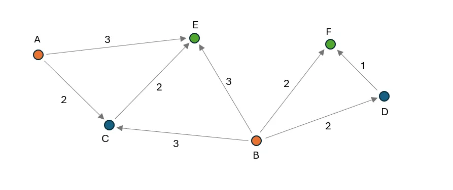
The image above illustrates a minimum cost flow optimization problem with six nodes and eight edges. Nodes A and B serve as sources, each with a supply of 50 units, while nodes E and F act as sinks, each with a demand of 40 units. Every edge has a maximum capacity of 25 units, with variable costs indicated in the image. The objective of the optimization is to allocate flow on each edge to move the required units from nodes A and B to nodes E and F, respecting the edge capacities at the lowest possible cost.
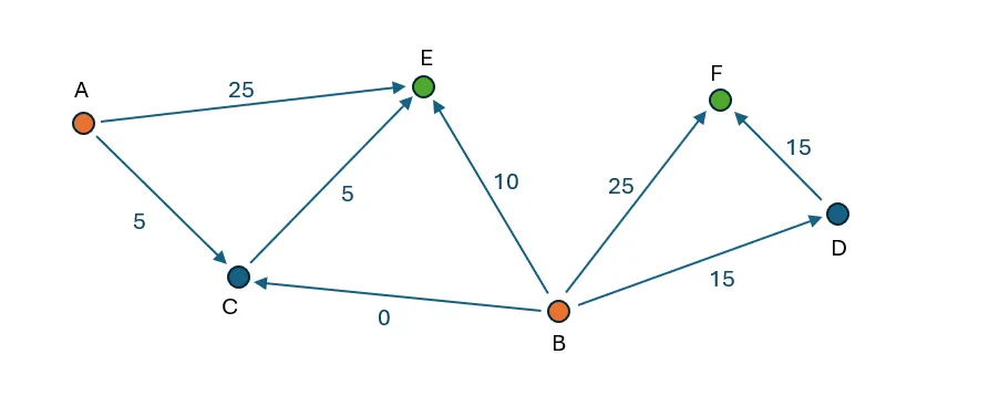
Node F can only receive supply from node B. There are two paths: directly or through node D. The direct path has a cost of 2, while the indirect path via D has a combined cost of 3. Thus, 25 units (the maximum edge capacity) are moved directly from B to F. The remaining 15 units are routed via B -D-F to meet the demand.
Currently, 40 out of 50 units have been transferred from node B, leaving a remaining supply of 10 units that can be moved to node E. The available pathways for supplying node E include: A-E and B-E with a cost of 3, A-C-E with a cost of 4, and B-C-E with a cost of 5. Consequently, 25 units are transported from A-E (limited by the edge capacity) and 10 units from B-E (limited by the remaining supply at node B). To meet the demand of 40 units at node E, an additional 5 units are moved via A-C-E, resulting in no flow being allocated to the B-C pathway.
Mathematical formulation
I introduce two mathematical formulations of minimum cost flow optimization:
1. LP (linear program) with continuous variables only
2. MILP (mixed integer linear program) with continuous and discrete variables
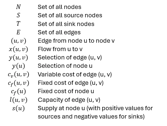
I am using following definitions:
LP formulation
This formulation only contains decision variables that are continuous, meaning they can have any value as long as all constraints are fulfilled. Decision variables are in this case the flow variables x(u, v) of all edges.
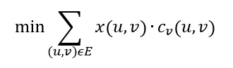
The objective function describes how the costs that are supposed to be minimized are calculated. In this case it is defined as the flow multiplied with the variable cost summed up over all edges:
Constraints are conditions that must be satisfied for the solution to be valid, ensuring that the flow does not exceed capacity limitations.
First, all flows must be non-negative and not exceed to edge capacities:

Flow conservation constraints ensure that the same amount of flow that goes into a node has to come out of the node. These constraints are applied to all nodes that are neither sources nor sinks:

For source and sink nodes the difference of out flow and in flow is smaller or equal the supply of the node:

If v is a source the difference of outflow minus inflow must not exceed the supply s(v). In case v is a sink node we do not allow that more than -s(v) can flow into the node than out of the node (for sinks s(v) is negative).
MILP
Additionally, to the continuous variables of the LP formulation, the MILP formulation also contains discreate variables that can only have specific values. Discrete variables allow to restrict the number of used nodes or edges to certain values. It can also be used to introduce fixed costs for using nodes or edges. In this article I show how to add fixed costs. It is important to note that adding discrete decision variables makes it much more difficult to find an optimal solution, hence this formulation should only be used if a LP formulation is not possible.
The objective function is defined as:

With three terms: variable cost of all edges, fixed cost of all edges, and fixed cost of all nodes.
The maximum flow that can be allocated to an edge depends on the edge’s capacity, the edge selection variable, and the origin node selection variable:

This equation ensures that flow can only be assigned to edges if the edge selection variable and the origin node selection variable are 1.
The flow conservation constraints are equivalent to the LP problem.
Implementation
In this section I explain how to implement a MILP optimization in Python. You can find the code in this repo.
Libraries
To build the flow network, I used NetworkX which is an excellent library (https://networkx.org/) for working with graphs. There are many interesting articles that demonstrate how powerful and easy to use NetworkX is to work with graphs, i.a. customizing NetworkX Graphs, NetworkX: Code Demo for Manipulating Subgraphs, Social Network Analysis with NetworkX: A Gentle Introduction.
One important aspect when building an optimization is to make sure that the input is correctly defined. Even one small error can make the problem infeasible or can lead to an unexpected solution. To avoid this, I used Pydantic to validate the user input and raise any issues at the earliest possible stage. This article gives an easy to understand introduction to Pydantic.
To transform the defined network into a mathematical optimization problem I used PuLP. Which allows to define all variables and constraint in an intuitive way. This library also has the advantage that it can use many different solvers in a simple pug-and-play fashion. This article provides good introduction to this library.
Defining nodes and edges
The code below shows how nodes are defined:
from pydantic import BaseModel, model_validator
from typing import Optional

# node and edge definitions
class Node(BaseModel, frozen=True):
    """
    class of network node with attributes:
    name: str - name of node
    demand: float - demand of node (if node is sink)
    supply: float - supply of node (if node is source)
    capacity: float - maximum flow out of node
    type: str - type of node
    x: float - x-coordinate of node
    y: float - y-coordinate of node
    fixed_cost: float - cost of selecting node
    """
    name: str
    demand: Optional[float] = 0.0
    supply: Optional[float] = 0.0
    capacity: Optional[float] = float('inf')
    type: Optional[str] = None
    x: Optional[float] = 0.0
    y: Optional[float] = 0.0
    fixed_cost: Optional[float] = 0.0

    @model_validator(mode='after')
    def validate(self):
        """
        validate if node definition are correct
        """
        # check that demand is non-negative
        if self.demand < 0 or self.demand == float('inf'): raise ValueError('demand must be non-negative and finite')
        # check that supply is non-negative
        if self.supply < 0: raise ValueError('supply must be non-negative')
        # check that capacity is non-negative
        if self.capacity < 0: raise ValueError('capacity must be non-negative')
        # check that fixed_cost is non-negative
        if self.fixed_cost < 0: raise ValueError('fixed_cost must be non-negative')
        return self
Nodes are defined through the Node class which is inherited from Pydantic’s BaseModel. This enables an automatic validation that ensures that all properties are defined with the correct datatype whenever a new object is created. In this case only the name is a required input, all other properties are optional, if they are not provided the specified default value is assigned to them. By setting the “frozen” parameter to True I made all properties immutable, meaning they cannot be changed after the object has been initialized.
The validate method is executed after the object has been initialized and applies more checks to ensure the provided values are as expected. Specifically it checks that demand, supply, capacity, variable cost and fixed cost are not negative. Furthermore, it also does not allow infinite demand as this would lead to an infeasible optimization problem.
These checks look trivial, however their main benefit is that they will trigger an error at the earliest possible stage when an input is incorrect. Thus, they prevent creating a optimization model that is incorrect. Exploring why a model cannot be solved would be much more time consuming as there are many factors that would need to be analyzed, while such “trivial” input error may not be the first aspect to investigate.
Edges are implemented as follows:
class Edge(BaseModel, frozen=True):
"""
class of edge between two nodes with attributes:
origin: 'Node' - origin node of edge
destination: 'Node' - destination node of edge
capacity: float - maximum flow through edge
variable_cost: float - cost per unit flow through edge
fixed_cost: float - cost of selecting edge
"""
origin: Node
destination: Node
capacity: Optional[float] = float('inf')
variable_cost: Optional[float] = 0.0
fixed_cost: Optional[float] = 0.0@model_validator(mode='after')
def validate(self):
"""
validate of edge definition is correct
"""
# check that node names are different
if self.origin.name == self.destination.name: raise ValueError('origin and destination names must be different')
# check that capacity is non-negative
if self.capacity < 0: raise ValueError('capacity must be non-negative')
# check that variable_cost is non-negative
if self.variable_cost < 0: raise ValueError('variable_cost must be non-negative')
# check that fixed_cost is non-negative
if self.fixed_cost < 0: raise ValueError('fixed_cost must be non-negative')
return self
The required inputs are an origin node and a destination node object. Additionally, capacity, variable cost and fixed cost can be provided. The default value for capacity is infinity which means if no capacity value is provided it is assumed the edge does not have a capacity limitation. The validation ensures that the provided values are non-negative and that origin node name and the destination node name are different.
Initialization of flowgraph object
To define the flowgraph and optimize the flow I created a new class called FlowGraph that is inherited from NetworkX’s DiGraph class. By doing this I can add my own methods that are specific to the flow optimization and at the same time use all methods DiGraph provides:
from networkx import DiGraph
from pulp import LpProblem, LpVariable, LpMinimize, LpStatus

class FlowGraph(DiGraph):
    """
    class to define and solve minimum cost flow problems
    """
    def __init__(self, nodes=[], edges=[]):
        """
        initialize FlowGraph object
        :param nodes: list of nodes
        :param edges: list of edges
        """
        # initialialize digraph
        super().__init__(None)

        # add nodes and edges
        for node in nodes: self.add_node(node)
        for edge in edges: self.add_edge(edge)


    def add_node(self, node):
        """
        add node to graph
        :param node: Node object
        """
        # check if node is a Node object
        if not isinstance(node, Node): raise ValueError('node must be a Node object')
        # add node to graph
        super().add_node(node.name, demand=node.demand, supply=node.supply, capacity=node.capacity, type=node.type,
                         fixed_cost=node.fixed_cost, x=node.x, y=node.y)


    def add_edge(self, edge):
        """
        add edge to graph
        @param edge: Edge object
        """
        # check if edge is an Edge object
        if not isinstance(edge, Edge): raise ValueError('edge must be an Edge object')
        # check if nodes exist
        if not edge.origin.name in super().nodes: self.add_node(edge.origin)
        if not edge.destination.name in super().nodes: self.add_node(edge.destination)

        # add edge to graph
        super().add_edge(edge.origin.name, edge.destination.name, capacity=edge.capacity,
                         variable_cost=edge.variable_cost, fixed_cost=edge.fixed_cost)
FlowGraph is initialized by providing a list of nodes and edges. The first step is to initialize the parent class as an empty graph. Next, nodes and edges are added via the methods add_node and add_edge. These methods first check if the provided element is a Node or Edge object. If this is not the case an error will be raised. This ensures that all elements added to the graph have passed the validation of the previous section. Next, the values of these objects are added to the Digraph object. Note that the Digraph class also uses add_node and add_edge methods to do so. By using the same method name I am overwriting these methods to ensure that whenever a new element is added to the graph it must be added through the FlowGraph methods which validate the object type. Thus, it is not possible to build a graph with any element that has not passed the validation tests.
Initializing the optimization problem
The method below converts the network into an optimization model, solves it, and retrieves the optimized values.
  def min_cost_flow(self, verbose=True):
        """
        run minimum cost flow optimization
        @param verbose: bool - print optimization status (default: True)
        @return: status of optimization
        """
        self.verbose = verbose

        # get maximum flow
        self.max_flow = sum(node['demand'] for _, node in super().nodes.data() if node['demand'] > 0)

        start_time = time.time()
        # create LP problem
        self.prob = LpProblem("FlowGraph.min_cost_flow", LpMinimize)
        # assign decision variables
        self._assign_decision_variables()
        # assign objective function
        self._assign_objective_function()
        # assign constraints
        self._assign_constraints()
        if self.verbose: print(f"Model creation time: {time.time() - start_time:.2f} s")

        start_time = time.time()
        # solve LP problem
        self.prob.solve()
        solve_time = time.time() - start_time

        # get status
        status = LpStatus[self.prob.status]

        if verbose:
            # print optimization status
            if status == 'Optimal':
                # get objective value
                objective = self.prob.objective.value()
                print(f"Optimal solution found: {objective:.2f} in {solve_time:.2f} s")
            else:
                print(f"Optimization status: {status} in {solve_time:.2f} s")

        # assign variable values
        self._assign_variable_values(status=='Optimal')

        return status
Pulp’s LpProblem is initialized, the constant LpMinimize defines it as a minimization problem — meaning it is supposed to minimize the value of the objective function. In the following lines all decision variables are initialized, the objective function as well as all constraints are defined. These methods will be explained in the following sections.
Next, the problem is solved, in this step the optimal value of all decision variables is determined. Following the status of the optimization is retrieved. When the status is “Optimal” an optimal solution could be found other statuses are “Infeasible” (it is not possible to fulfill all constraints), “Unbounded” (the objective function can have an arbitrary low values), and “Undefined” meaning the problem definition is not complete. In case no optimal solution was found the problem definition needs to be reviewed.
Finally, the optimized values of all variables are retrieved and assigned to the respective nodes and edges.
Defining decision variables
All decision variables are initialized in the method below:
   def _assign_variable_values(self, opt_found):
        """
        assign decision variable values if optimal solution found, otherwise set to None
        @param opt_found: bool - if optimal solution was found
        """
        # assign edge values
        for _, _, edge in super().edges.data():
            # initialize values
            edge['flow'] = None
            edge['selected'] = None
            # check if optimal solution found
            if opt_found and edge['flow_var'] is not None:
                edge['flow'] = edge['flow_var'].varValue

                if edge['selection_var'] is not None:
                    edge['selected'] = edge['selection_var'].varValue

        # assign node values
        for _, node in super().nodes.data():
            # initialize values
            node['selected'] = None
            if opt_found:
                # check if node has selection variable
                if node['selection_var'] is not None:
                    node['selected'] = node['selection_var'].varValue
First it iterates through all edges and assigns continuous decision variables if the edge capacity is greater than 0. Furthermore, if fixed costs of the edge are greater than 0 a binary decision variable is defined as well. Next, it iterates through all nodes and assigns binary decision variables to nodes with fixed costs. The total number of continuous and binary decision variables is counted and printed at the end of the method.
Defining objective
After all decision variables have been initialized the objective function can be defined:
    def _assign_objective_function(self):
        """
        define objective function
        """
        objective = 0

        # add edge costs
        for _, _, edge in super().edges.data():
            if edge['selection_var'] is not None: objective += edge['selection_var'] * edge['fixed_cost']
            if edge['flow_var'] is not None: objective += edge['flow_var'] * edge['variable_cost']

        # add node costs
        for _, node in super().nodes.data():
            # add node selection costs
            if node['selection_var'] is not None: objective += node['selection_var'] * node['fixed_cost']

        self.prob += objective, 'Objective',
The objective is initialized as 0. Then for each edge fixed costs are added if the edge has a selection variable, and variable costs are added if the edge has a flow variable. For all nodes with selection variables fixed costs are added to the objective as well. At the end of the method the objective is added to the LP object.
Defining constraints
All constraints are defined in the method below:
  def _assign_constraints(self):
        """
        define constraints
        """
        # count of contraints
        constr_count = 0
        # add capacity constraints for edges with fixed costs
        for origin_name, destination_name, edge in super().edges.data():
            # get capacity
            capacity = edge['capacity'] if edge['capacity'] < float('inf') else self.max_flow
            rhs = capacity
            if edge['selection_var'] is not None: rhs *= edge['selection_var']
            self.prob += edge['flow_var'] <= rhs, f"capacity_{origin_name}-{destination_name}",
            constr_count += 1

            # get origin node
            origin_node = super().nodes[origin_name]
            # check if origin node has a selection variable
            if origin_node['selection_var'] is not None:
                rhs = capacity * origin_node['selection_var']
                self.prob += (edge['flow_var'] <= rhs, f"node_selection_{origin_name}-{destination_name}",)
                constr_count += 1

        total_demand = total_supply = 0
        # add flow conservation constraints
        for node_name, node in super().nodes.data():
            # aggregate in and out flows
            in_flow = 0
            for _, _, edge in super().in_edges(node_name, data=True):
                if edge['flow_var'] is not None: in_flow += edge['flow_var']

            out_flow = 0
            for _, _, edge in super().out_edges(node_name, data=True):
                if edge['flow_var'] is not None: out_flow += edge['flow_var']

            # add node capacity contraint
            if node['capacity'] < float('inf'):
                self.prob += out_flow = demand - supply
                rhs = node['demand'] - node['supply']
                self.prob += in_flow - out_flow >= rhs, f"flow_balance_{node_name}",
            constr_count += 1

            # update total demand and supply
            total_demand += node['demand']
            total_supply += node['supply']

        if self.verbose:
            print(f"Constraints: {constr_count}")
            print(f"Total supply: {total_supply}, Total demand: {total_demand}")
First, capacity constraints are defined for each edge. If the edge has a selection variable the capacity is multiplied with this variable. In case there is no capacity limitation (capacity is set to infinity) but there is a selection variable, the selection variable is multiplied with the maximum flow that has been calculated by aggregating the demand of all nodes. An additional constraint is added in case the edge’s origin node has a selection variable. This constraint means that flow can only come out of this node if the selection variable is set to 1.
Following, the flow conservation constraints for all nodes are defined. To do so the total in and outflow of the node is calculated. Getting all in and outgoing edges can easily be done by using the in_edges and out_edges methods of the DiGraph class. If the node has a capacity limitation the maximum outflow will be constraint by that value. For the flow conservation it is necessary to check if the node is either a source or sink node or a transshipment node (demand equals supply). In the first case the difference between inflow and outflow must be greater or equal the difference between demand and supply while in the latter case in and outflow must be equal.
The total number of constraints is counted and printed at the end of the method.
Retrieving optimized values
After running the optimization, the optimized variable values can be retrieved with the following method:
    def _assign_variable_values(self, opt_found):
        """
        assign decision variable values if optimal solution found, otherwise set to None
        @param opt_found: bool - if optimal solution was found
        """
        # assign edge values
        for _, _, edge in super().edges.data():
            # initialize values
            edge['flow'] = None
            edge['selected'] = None
            # check if optimal solution found
            if opt_found and edge['flow_var'] is not None:
                edge['flow'] = edge['flow_var'].varValue

                if edge['selection_var'] is not None:
                    edge['selected'] = edge['selection_var'].varValue

        # assign node values
        for _, node in super().nodes.data():
            # initialize values
            node['selected'] = None
            if opt_found:
                # check if node has selection variable
                if node['selection_var'] is not None:
                    node['selected'] = node['selection_var'].varValue
This method iterates through all edges and nodes, checks if decision variables have been assigned and adds the decision variable value via varValue to the respective edge or node.
Demo
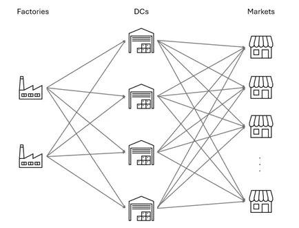
To demonstrate how to apply the flow optimization I created a supply chain network consisting of 2 factories, 4 distribution centers (DC), and 15 markets. All goods produced by the factories have to flow through one distribution center until they can be delivered to the markets.
Node properties were defined:
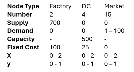
Ranges mean that uniformly distributed random numbers were generated to assign these properties. Since Factories and DCs have fixed costs the optimization also needs to decide which of these entities should be selected.
Edges are generated between all Factories and DCs, as well as all DCs and Markets. The variable cost of edges is calculated as the Euclidian distance between origin and destination node. Capacities of edges from Factories to DCs are set to 350 while from DCs to Markets are set to 100.
The code below shows how the network is defined and how the optimization is run:
# Define nodes
factories = [Node(name=f'Factory {i}', supply=700, type='Factory', fixed_cost=100, x=random.uniform(0, 2),
                  y=random.uniform(0, 1)) for i in range(2)]
dcs = [Node(name=f'DC {i}', fixed_cost=25, capacity=500, type='DC', x=random.uniform(0, 2),
            y=random.uniform(0, 1)) for i in range(4)]
markets = [Node(name=f'Market {i}', demand=random.randint(1, 100), type='Market', x=random.uniform(0, 2),
                y=random.uniform(0, 1)) for i in range(15)]

# Define edges
edges = []
# Factories to DCs
for factory in factories:
    for dc in dcs:
        distance = ((factory.x - dc.x)**2 + (factory.y - dc.y)**2)**0.5
        edges.append(Edge(origin=factory, destination=dc, capacity=350, variable_cost=distance))

# DCs to Markets
for dc in dcs:
    for market in markets:
        distance = ((dc.x - market.x)**2 + (dc.y - market.y)**2)**0.5
        edges.append(Edge(origin=dc, destination=market, capacity=100, variable_cost=distance))

# Create FlowGraph
G = FlowGraph(edges=edges)

G.min_cost_flow()
The output of flow optimization is as follows:
Variable types: 68 continuous, 6 binary
Constraints: 161
Total supply: 1400.0, Total demand: 909.0
Model creation time: 0.00 s
Optimal solution found: 1334.88 in 0.23 s
The problem consists of 68 continuous variables which are the edges’ flow variables and 6 binary decision variables which are the selection variables of the Factories and DCs. There are 161 constraints in total which consist of edge and node capacity constraints, node selection constraints (edges can only have flow if the origin node is selected), and flow conservation constraints. The next line shows that the total supply is 1400 which is higher than the total demand of 909 (if the demand was higher than the supply the problem would be infeasible). Since this is a small optimization problem, the time to define the optimization model was less than 0.01 seconds. The last line shows that an optimal solution with an objective value of 1335 could be found in 0.23 seconds.
Additionally, to the code I described in this post I also added two methods that visualize the optimized solution. The code of these methods can also be found in the repo.
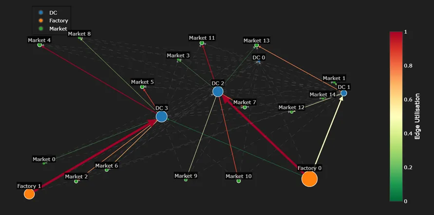
All nodes are located by their respective x and y coordinates. The node and edge size is relative to the total volume that is flowing through. The edge color refers to its utilization (flow over capacity). Dashed lines show edges without flow allocation.
In the optimal solution both Factories were selected which is inevitable as the maximum supply of one Factory is 700 and the total demand is 909. However, only 3 of the 4 DCs are used (DC 0 has not been selected).
In general the plot shows the Factories are supplying the nearest DCs and DCs the nearest Markets. However, there are a few exceptions to this observation: Factory 0 also supplies DC 3 although Factory 1 is nearer. This is due to the capacity constraints of the edges which only allow to move at most 350 units per edge. However, the closest Markets to DC 3 have a slightly higher demand, hence Factory 0 is moving additional units to DC 3 to meet that demand. Although Market 9 is closest to DC 3 it is supplied by DC 2. This is because DC 3 would require an additional supply from Factory 0 to supply this market and since the total distance from Factory 0 over DC 3 is longer than the distance from Factory 0 through DC 2, Market 9 is supplied via the latter route.
Another way to visualize the results is via a Sankey diagram which focuses on visualizing the flows of the edges:
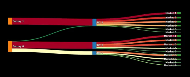
The colors represent the edges’ utilizations with lowest utilizations in green changing to yellow and red for the highest utilizations. This diagram shows very well how much flow goes through each node and edge. It highlights the flow from Factory 0 to DC 3 and also that Market 13 is supplied by DC 2 and DC 1.
Summary
Minimum cost flow optimizations can be a very helpful tool in many domains like logistics, transportation, telecommunication, energy sector and many more. To apply this optimization it is important to translate a physical system into a mathematical graph consisting of nodes and edges. This should be done in a way to have as few discrete (e.g. binary) decision variables as necessary as those make it significantly more difficult to find an optimal solution. By combining Python’s NetworkX, Pulp and Pydantic libraries I built an flow optimization class that is intuitive to initialize and at the same time follows a generalized formulation which allows to apply it in many different use cases. Graph and flow diagrams are very helpful to understand the solution found by the optimizer.
If not otherwise stated all images were created by the author.